
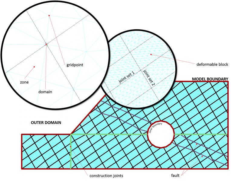
UDEC is different from conventional numerical programs in the way the model geometry is created. A single block is created first, with a size that encompasses the physical region being analyzed. Then, this block is cut into smaller blocks whose boundaries represent both geologic features and engineered structures in the model. This cutting process is termed collectively as joint generation; however, “joints” represent both physically real geologic structures and boundaries of artificial structures or materials that will be removed or changed during the subsequent stages of the UDEC analysis. In this latter case, the joints are fictitious entities (i.e., construction joints) and their presence should not influence model results.
Blocks
The initial block(s) can be defined as a simple rectangular box or circular domain, using a reference image (*.dxf, *.png, *.jpg, *.gif), as a table of coordinates or importing a formatted ASCII data file of UDEC blocks (*.dat). Blocks can be subsequently edited to move, insert or delete points interactively or a table of point coordinates.
Joints
Joints or discontinuities can be defined in UDEC with commands, FISH functions or interactively using the graphical user interface via:
- Individual cracks;
- Basic shapes (e.g., circle, arc, line, box, etc.);
- Tables of two-dimensional coordinates;
- Statistical joint-set generator; and
- Voronoi tessellation generator.
In addition, any joint can be welded (joined) together to create construction joints while minimizing their effects on the model behavior. These cracks are normally used to define excavation boundaries and to provide zone density control.
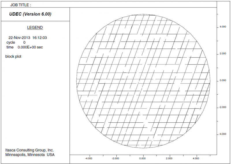
Statistical Joint-Set Generator
The joint generator in UDEC define a joint-set in terms of its angle (CCW from the x-axis), gap length, spacing, trace length and origin. In addition to a mean value, the maximum random deviation from the mean (for uniform probability distribution) can be specified. Joint generation can be limited to selected portions of the model by defining a limiting range. Blocks may also be hidden (and later shown) to remove them from a joint generation stage.
Discontinuous joints can be generated by specifying the mean gap between each joint segment and their trace length. By default, all joint segments terminating within a block will be deleted once the blocks are zoned or model calculations begin. However, it is possible to simulate this scenario by creating continuous joints and defining joint properties and intact rock properties intermittently along their length.
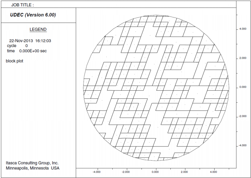
Voronoi Tessellation Generator
Voronoi tessellation creates randomly sized polygonal or triangular blocks. One or more blocks in a UDEC model can be subdivided into Voronoi sub-blocks of arbitrary size. This joint generator is useful to simulate crack propagation; “fracturing” occurs when the joint strength between Voronoi blocks is exceeded. Such a model is often referred to as a UDEC -DM (damage model) and used to simulate intact rock undergoing micro-damage.
The Voronoi algorithm begins by distributing points randomly within the tessellation region. The interior points are then allowed to move. An iteration procedure moves the points; the higher the number of iterations, the more uniform the spacing between points will be. Next, triangles are created between all points. Finally, the Voronoi polygons are created by constructing perpendicular bisectors of all triangles that share a common side. The polygons are truncated at the boundaries of the tessellation region.
Zones
A model may contain both rigid and deformable blocks at the same time. Blocks are rigid by default, but can be made deformable by discretized them automatically or manually into triangular finite-difference zones. Zone generation can be accomplished using the following.
TRIANGULAR MESH - Automatic generation of zones for an arbitrarily shaped block.
QUADRILATERAL MESH - Automatic generation of diagonally opposed triangular zones to improve plastic flow calculation. This form of zoning will not work for all block shapes; blocks must contain 4 or 5 corners.
MIXED MESH - Subdivides existing triangular zones into 3 subzones with an overlay of 4 zones (12 total) to improve plastic flow calculation. The strain of these zones is averaged to avoid hourglass effects.
SINGLE MESH - Mixed mesh, but only with a single layer of zones (i.e., no overlay).
MANUAL MESHING - For manual generation, a list of gridpoints and zones must be specified. Manual generation must be performed for each individual block.